Axial Piston Pump – Installation, Operation & Maintenance Manual
This manual provides official installation, operation, shutdown, cleaning, and maintenance instructions for Rohre axial piston high pressure pumps.
Compliance with this manual is mandatory to ensure safe operation, system reliability, and long service life.
CE Approval NB2292
Table of Contents
Axial Piston Pump Operating Precautions
This manual provides installation, operation, shutdown, cleaning, and maintenance instructions for Rohre axial piston high pressure pumps.
Strict compliance with this manual is essential to ensure:
Safe operation
Reliable performance
Long service life
Prevention of abnormal wear or damage
⚠ The pump shall only be operated within the limits specified in this manual.
Pump Rotation Direction
The pump housing is fitted with a rotation direction indicator label.
Always follow the arrow direction indicated on the pump body.
Port identification:
I – Inlet port
O – Outlet port
Incorrect rotation direction may cause severe damage to internal pump components.
Inlet Pressure Requirements
The recommended inlet pressure of the pump shall be maintained within the range of 2.5 bar to 5 bar.
When the inlet pressure is below 1 bar, the working fluid is highly susceptible to cavitation, which may lead to serious pump damage.The inlet water supply flow rate shall be greater than 1.2 times the rated flow of the axial piston pump.
Operation under insufficient inlet flow conditions is strictly prohibited.The inlet pipeline must not restrict the flow required by the axial piston pump.
Avoid the use of sharp bends and small-diameter piping.
For long-distance water supply, large-diameter pipelines are strongly recommended.Pressure measuring instruments shall be installed downstream of the inlet filter, as close as possible to the pump inlet.
The working fluid entering the pump must be filtered prior to entering the pump body.
The inlet piping must be completely sealed.
All connections shall be free of air leakage to prevent air ingress into the pump.Inlet pressure shall never exceed outlet pressure.
Notes
Recommended inlet pressure: 2.5–5 bar
Inlet pressure below 1 bar is strictly prohibited, as it may cause cavitation.
Temperature Limits
Working fluid temperature: +2 °C to +50 °C
Ambient temperature: +2 °C to +50 °C
Operation outside the above temperature ranges may adversely affect pump performance and service life.
Filtration Requirements
Proper filtration is critical to extending the service life of the pump.
Therefore, careful selection of the filter is essential.
Filter Material Compatibility
The filter material shall be compatible with the working fluid.
For example, filters unsuitable for acidic or chemically aggressive fluids must not be used.
The chemical composition of the selected filter material must be clearly understood.
Filtration Accuracy
For axial piston pumps, the filtration requirements are as follows:
Filtration rating: 10 μm
Filtration efficiency: β10 > 5000
Pressure Loss Monitoring
The pressure loss across the filter shall be monitored, and sufficient inlet pressure margin shall be ensured.
Filter Maintenance
Filters shall be inspected, cleaned, or replaced regularly to prevent:
Filter blockage
Insufficient filtration accuracy
Noise Control
The use of flexible hoses can effectively minimize vibration and noise transmission.
Since noise generated by the pump (assembly) is transmitted through the pump mounting base to the entire system, proper vibration isolation components are essential to reduce noise and vibration.
Noise level is influenced by the following factors:
Pump speed – higher speeds generate higher noise levels
Installation rigidity – rigid mounting produces more noise than elastic mounting
Piping connection – rigid piping directly connected to the pump increases noise
Pressure level – higher pressure results in higher noise
Air Vent
Removing air from the pump body is critical for normal pump operation.
Before operating the pump, loosen the air vent screw on the pump housing to release internal air, then tighten it securely.
The longer the inlet pipeline, the longer the venting time required.For working fluids that may generate gas during operation, it is recommended to install a venting pipeline at the vent port to allow continuous air discharge.
(The vent line may be routed back to the water tank.)After the pump has been in operation and it is confirmed that the pump body remains fully filled with water with no air ingress, the pump may be restarted directly without venting.
If negative pressure occurs in the inlet pipeline or the pump body experiences water shortage, air venting must be performed again before restarting.
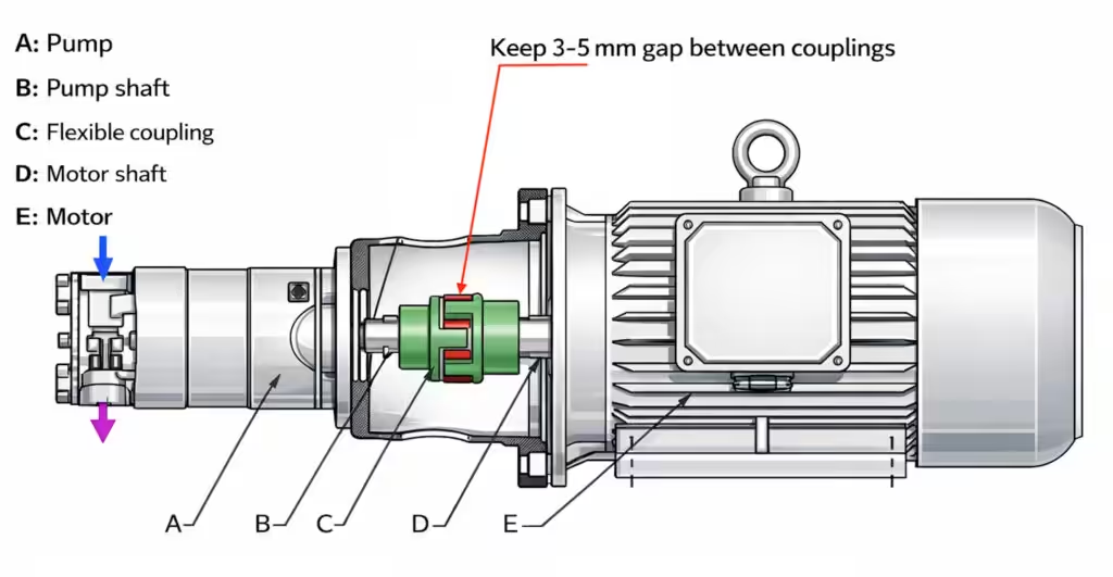
Coupling Installation Clearance
Maintain a clearance of 3–5 mm between couplings.
The diagram illustrates correct installation and alignment between the pump and the motor:
A – Pump
B – Pump shaft
C – Flexible coupling
D – Motor shaft
Port identification:
1 – Outlet check valve
2 – Inlet connection
⚠ Important Notes
Maintain a 3–5 mm clearance between couplings (including elastomer elements).
Inlet and outlet connections must not be reversed.
Incorrect installation may result in dry friction and severe damage.The blue arrow in the diagram indicates the pump inlet; the red arrow indicates the pump outlet.
No axial or radial load is permitted on the pump shaft.
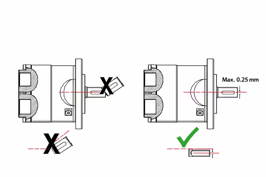
Shaft Alignment and Installation Requirements
Maintain a 3–5 mm clearance between couplings (including flexible coupling elements).
The misalignment between the pump shaft and motor shaft shall not exceed 0.25 mm.
Installation of the pump and motor must not be performed using force or tools.
The shaft geometry and coupling dimensions must be clearly verified prior to installation.Verify the corresponding installation tolerances and strictly follow the recommended coupling installation tolerances.
⚠ No axial or radial load is allowed on the pump shaft.
It is strongly recommended to use a flexible coupling between the motor and the pump.
After installation, ensure proper shaft alignment so that the axial piston pump shaft is not subjected to axial or radial forces.
Rotation Direction Verification
The rotation direction of the axial piston pump must be consistent with the arrow marked on the pump body.
Before checking motor rotation:
Ensure outlet pressure is below 2.5 bar
Do not operate the pump under pressure during rotation direction verification
If the pump outlet is heavy, additional support brackets shall be installed as shown in the diagram.
Pre-Startup Inspection
Before starting the axial piston pump, carefully verify the following:
Confirm all nameplate data (flow rate, pressure, etc.) meet the design requirements.
Confirm inlet pressure is ≥ 2.5 bar, and appropriate dry-run protection measures are in place.
Confirm inlet and outlet connections are correctly installed.
Confirm all pipelines and fittings are made of materials that will not cause rust or scale formation.
Confirm the inlet pipeline can provide sufficient inlet flow
(check pipe diameter, water tank capacity, and inlet piping restriction).Confirm the working fluid entering the pump has been filtered
(solid particle size < 0.01 mm).Confirm there are no dead-end conditions in the discharge piping and that overpressure protection is provided.
Confirm all pipelines are clean and free of debris, hair, or foreign matter.
Confirm motor rotation direction is correct and vibration isolation is properly installed.
⚠ During installation and operation, the pump must not be subjected to any axial or radial load.
Coupling Installation Procedure
Install the flexible coupling onto the motor shaft and pump shaft, ensuring smooth installation without impact or force.
After installation, verify:
Coupling clearance between pump and motor shafts is approximately 3–5 mm
Axial clearance between coupling ends and shaft shoulders is > 3 mm
Coupling bolts are securely tightened
During static and dynamic operation, ensure the coupling does not interfere with surrounding components.
Before startup, loosen the air vent screw to discharge air until water flows out continuously, then retighten the screw.
⚠ Axial piston pumps use water as the lubricating medium.
No additional lubricating oil is required or permitted.
During operation, the pump must remain fully filled with water.
⚠ Dry running is strictly prohibited.
Operating the pump without water will cause severe overheating and damage.
Pump Startup
Correctly install inlet and outlet connections and piping.
Sealing shall be achieved using O-rings or flat gaskets.
If rubber gaskets are used, the gasket thickness must be strictly controlled.Before startup, ensure the pump body is fully filled with water and sufficient inlet water is available.
Loosen the air vent screw on the pump side to discharge air.
It is recommended to perform air venting twice.Open the discharge piping.
Start the pump and run it for approximately 60 seconds at an inlet pressure of 2.5–5 bar.
Observe the outlet flow, vibration, and noise.If no abnormal flow, vibration, or noise is observed, the pump may be put into continuous operation.
The pump must not be started with the discharge valve closed, as this may trigger safety valves or cause pipeline rupture.
If the pump shuts down due to water supply interruption or insufficient inlet pressure, stop the pump immediately.
Before restarting, air venting must be performed again following the above procedure.
⚠ Note:
For initial startup of a new pump, it is recommended to operate under zero-pressure or low-pressure conditions.
Pump Shutdown
During normal operation, the pump shall be shut down gradually
(reduce speed from high speed to low speed before stopping).In emergency situations, an immediate cut-off emergency shutdown shall be performed to minimize pump damage.
Gradual shutdown is strictly prohibited under insufficient or no inlet water conditions.Normal shutdown sequence:
Stop the pump first
Wait until the pump has completely stopped
Then shut off the water supply
In emergency conditions, perform a braking-type emergency shutdown, and all operations shall cease immediately.
Maintenance and Service
After initial startup or shutdown, it is recommended to flush the internal pump components with fresh water.
After every 4000 hours of operation, all components shall be inspected.
If replacement or repair is required, the axial piston pump shall be returned to the Rohre manufacturer.
Axial Piston Pump Shutdown Instructions
Normal Shutdown
During normal operation, the axial piston high pressure pump shall be shut down gradually.
The pump speed shall be reduced progressively from the normal operating speed to a low speed, followed by a complete stop.
Gradual deceleration is required to prevent pressure shock, excessive mechanical stress, and internal component damage.
Emergency Shutdown
In the event of an emergency, the axial piston pump shall be stopped immediately by cutting off the power supply in order to minimize potential damage to the pump and drive system.
Gradual shutdown is strictly prohibited if the inlet water supply is insufficient or unavailable, as this may cause cavitation or dry running.
Normal Shutdown Sequence for Axial Piston Pump Systems
For normal shutdown of an axial piston high pressure pump system, the following sequence shall be observed:
Stop the axial piston high pressure pump first.
After the pump has come to a complete standstill, shut down the feed water pump.
This shutdown sequence ensures adequate lubrication and prevents dry running or internal wear of the axial piston assembly.
Emergency Power-Off Shutdown
In emergency conditions, an immediate power-off shutdown shall be performed.
All pump operation must cease without delay.
Emergency shutdown shall override all normal operating procedures.
Cleaning After Shutdown
After normal shutdown or long-term shutdown, the axial piston high pressure pump must be properly flushed and cleaned.
Detailed procedures are provided in the Pump Cleaning and Flushing Instructions section of this manual.
Pump Cleaning and Flushing Guidelines
Contaminants commonly found in water treatment applications include metal oxides, calcium-containing deposits, organic substances, and biological matter.
Pump contamination refers to deposits adhering to pump components, including scale and precipitated solids originating from the process fluid.
The purpose of pump cleaning and flushing is to minimize contamination on internal components, thereby reducing abnormal wear and extending pump service life.
General Description
During normal operation, internal pump components are exposed to contamination from inorganic salts, microorganisms, colloidal particles, and insoluble organic substances.
These contaminants may adhere to component surfaces during operation, resulting in:
abnormal mechanical wear,
reduced volumetric efficiency,
shortened service life, and
progressive degradation of pump performance.
To mitigate these effects, it is recommended that the flushing interval shall not exceed 24 hours.
Cleaning Safety Precautions
During flushing, the pump shall operate either under normal operating conditions or at low pressure.
During operation or flushing circulation (using clean water), the fluid temperature shall not exceed 50 °C.
After pump shutdown, the axial piston pump shall be flushed with fresh water to prevent crystallization of the process fluid or corrosion of internal components.
For acidic or alkaline process fluids, it is strongly recommended that the axial piston high pressure pump be flushed with clean water once every 24 hours.
Operate the pump at low pressure.
Set the rotational speed to 600–800 RPM.
Maintain flushing operation for 5–10 minutes.
For applications involving high acidity/alkalinity or fluids prone to crystallization, the flushing interval shall be shortened, and the flushing frequency shall be increased accordingly.
Pump Automatic Air Vent
Due to factors such as insufficient flushing intervals, high raw water density, inlet piping length and bends, and site installation constraints, air may accumulate within the pump and the safety filter.
Over time, trapped air can lead to:
unstable pump operation
abnormal wear of internal components
potential damage to the axial piston pump
To mitigate air accumulation and reduce abnormal wear, it is strongly recommended to install an automatic air vent at appropriate locations in the inlet system.
Proper air venting significantly reduces the risk of air pockets and improves operational stability.
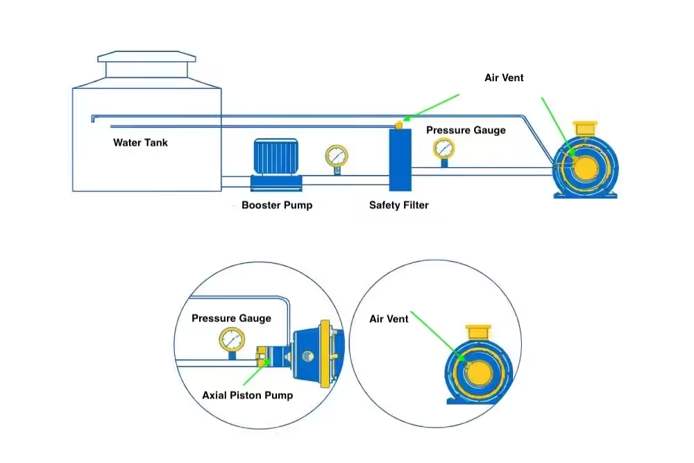
Typical Layout of Air Vent for Axial Piston Pump
(Schematic illustration – air vent installed on inlet piping upstream of the pump)
The air vent shall be installed at the highest point of the inlet pipeline wherever possible.
Three Critical Operating Precautions
Inlet Water Pressure
The minimum inlet water pressure shall be greater than 2 bar, and sufficient inlet flow must be ensured at all times.
Water Quality and Filtration
Water quality must be properly controlled.
Particles larger than 0.01 mm shall not be allowed to enter the pump.
Adequate pre-filtration is mandatory to protect internal axial piston components.
Air-Free Operation
No air shall be present inside the pump during operation.
Air ingress must be strictly avoided to prevent aeration-related damage and cavitation.