
TT-200, TT-694 & TT-694S · OEM equipment
Firefighting Water Mist Turbines
Freshwater and seawater configurations for fixed fire protection. Select the water duty, aiming range and control package your system needs.
Freshwater and seawater configurations for fire equipment manufacturers and system integrators.
Choose the configuration
Start with the duty. Then define the package.
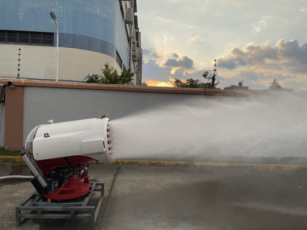
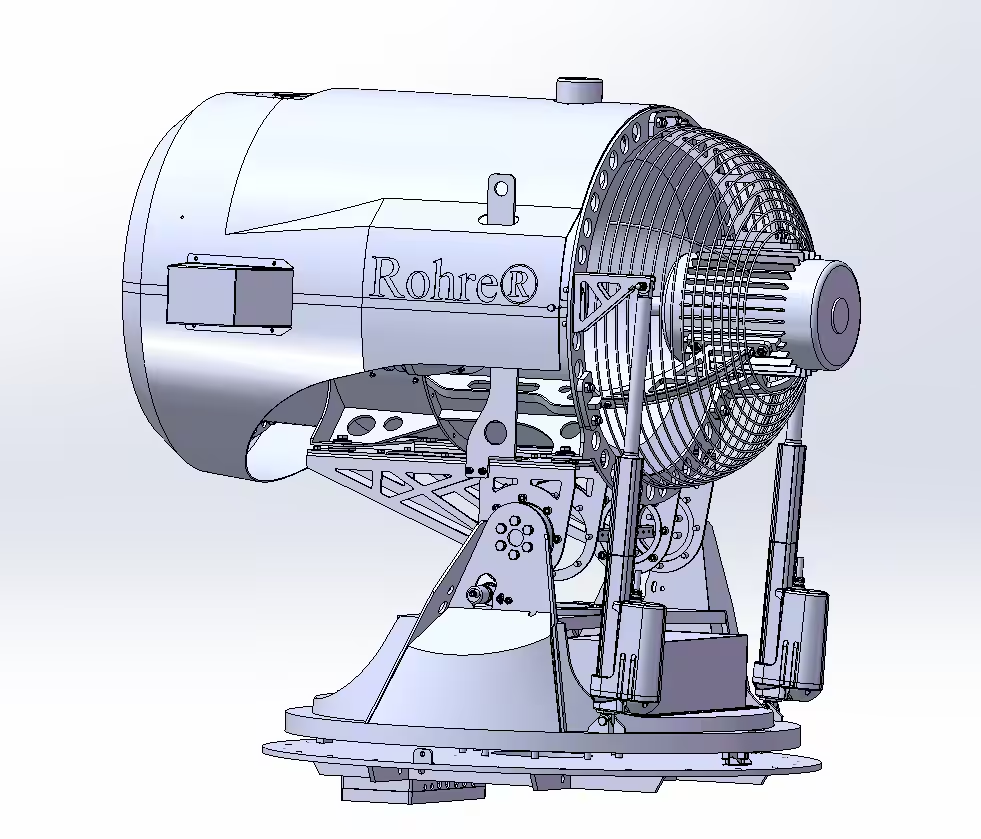
A fan projects the water spray toward the selected area, while the positioning mechanism sets the discharge direction. Flow, nozzle arrangement and movement limits depend on the model.
TT-200
Freshwater
DN50 inlet, an 18-nozzle water ring and a +10° to −85° elevation range. Review this configuration where the installation requires a downward aiming envelope.
Enquire about TT-200TT-694
Freshwater
DN100 inlet, a DN65 center nozzle and a +45° to −25° elevation range. The center nozzle is not independently operated in the listed configuration.
Enquire about TT-694TT-694S
Seawater · Offshore platforms
DN100 inlet, a DN65 center nozzle and a +45° to −25° elevation range. The same listed operating parameters as TT-694, configured for seawater service on offshore platforms. All seawater-wetted parts are made of SAF 2507 super-duplex stainless steel.
Enquire about TT-694SHow the turbine delivers directional water mist
1. Water discharge
Water is discharged through the selected nozzle arrangement. Nozzle geometry and water pressure influence the spray characteristics.
2. Fan-assisted projection
The electrically driven fan carries the spray toward the target area. Wind and obstructions affect where water is delivered.
3. Positioning
The rotary and tilt mechanisms set the aiming direction within the model’s travel limits. The selected controls determine how commands and feedback are handled.
Equipment & product videos
See the equipment. Watch it operate.
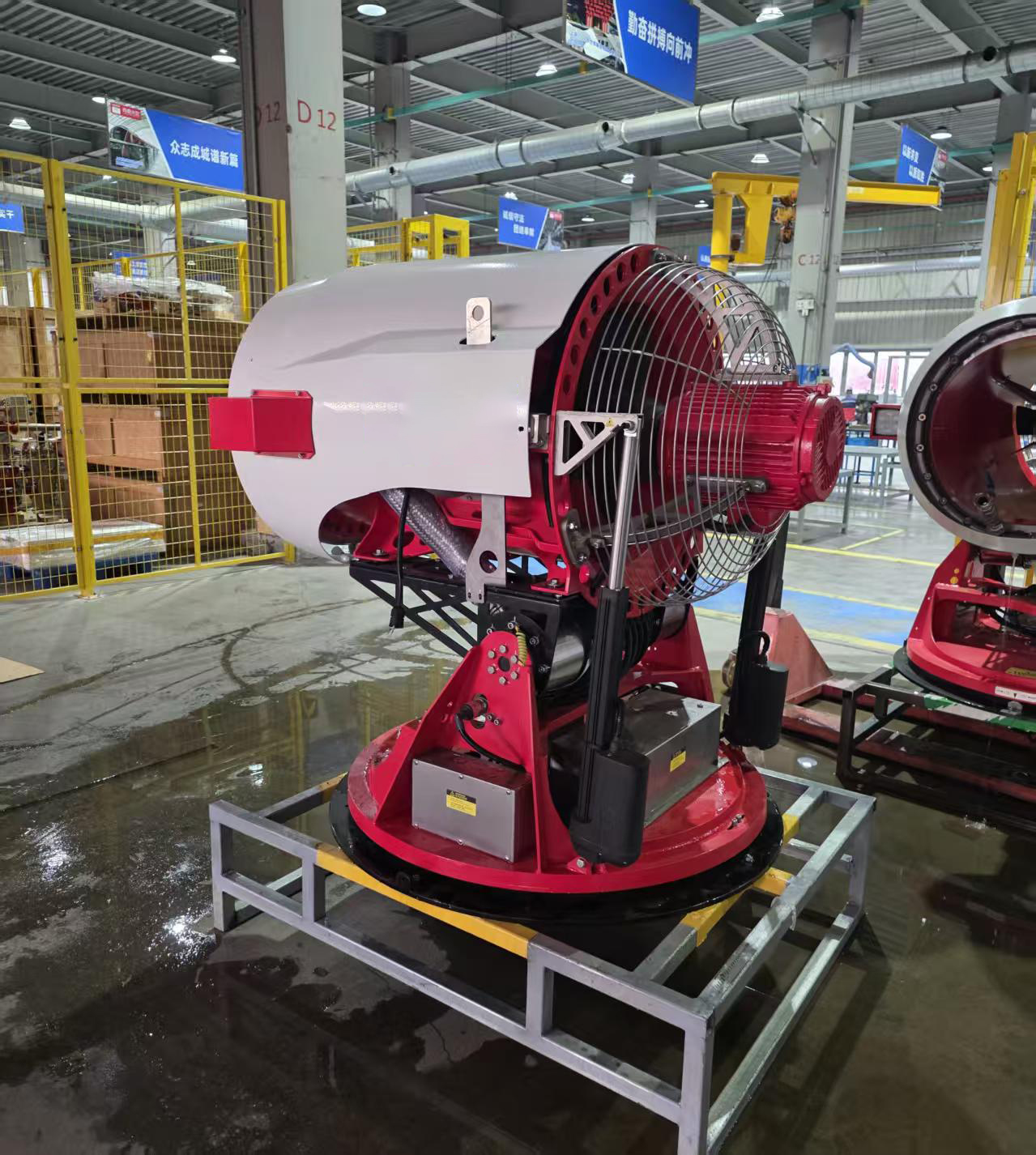
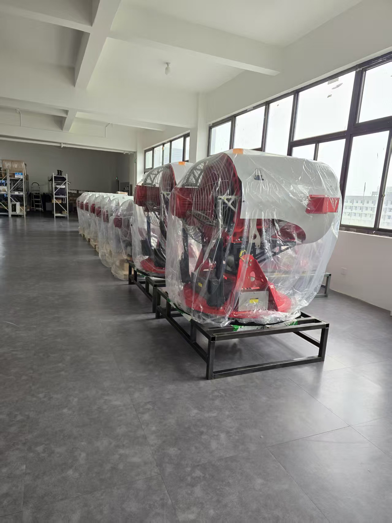
Inspect the fan drive, positioning base and support frame in the workshop photograph, then watch the nozzle ring and outdoor water discharge in the videos below.
For installation dimensions, use the approved drawing for your selected model.
Water mist turbine manufacturer
A product video showing the nozzle ring and outdoor water discharge from several viewpoints. Duration: 23 seconds.
Firefighting turbine testing
Outdoor spray footage with a close-up of water leaving the nozzle ring. Duration: 10 seconds.
These videos demonstrate water discharge. Model-specific flow, pressure and application performance must be assessed against the documented test conditions.
Application engineering
Plan around the actual fire risk.
Tell us what needs protection, where the turbine can be installed and what the fire protection system must achieve.
Substations & transformers
Design question: Can the spray reach the transformer and exposed adjacent equipment from the proposed mounting point? Review electrical clearances, oil containment, isolation strategy and obstructions. Energized-equipment use needs specific suitability evidence.
Timber & wood processing
Design question: Will changing pile height, conveyors or stored material block the spray path? Assess exposed faces, shielding, wind and the ability to aim at the required zones. Spray reach alone does not establish penetration into a material pile.
Industrial facilities
Design question: Is the objective to cool equipment, limit fire spread or extinguish a defined hazard? Map the fuel load, machinery and access routes so the equipment specification supports that objective.
Tank farms & fuel handling
Design question: Is the duty exposure cooling or flammable-liquid extinguishing? Tank height, separation, bund geometry, wind and drainage shape the design. The listed turbine equipment does not establish foam compatibility or liquid-fire extinguishing capability.
Chemical & process plants
Design question: Is water an appropriate agent for the substances present? Confirm water compatibility, area classification, equipment exposure and runoff management before defining the turbine configuration.
Offshore platforms
TT-694S is the seawater configuration for offshore platform applications, with the same listed operating parameters as TT-694. Provide the seawater supply conditions, mounting arrangement, electrical supply and control requirements for the project review.
These are application review categories, not a claim that every configuration is approved for every hazard. Foam use, hazardous-area operation and electrical safety require separate confirmation.
Technical data
The parameters that guide your selection.
Compare the TT-200 and TT-694 freshwater configurations with TT-694S for seawater service on offshore platforms. TT-694S shares the listed operating parameters of TT-694.
| Parameter | TT-200 | TT-694 | TT-694S |
|---|---|---|---|
| Rated water flow | 200 L/min · 12 m³/h | 694 L/min · 41.64 m³/h | 694 L/min · 41.64 m³/h |
| Rated operating pressure | 1.2 MPa · 12 bar | 1.2 MPa · 12 bar | 1.2 MPa · 12 bar |
| Water medium | Fresh water | Fresh water | Seawater |
| Water inlet | DN50 · quick coupling | DN100 | DN100 |
| Discharge arrangement | 18-nozzle ring; no center nozzle | DN65 center nozzle, non-independent type | DN65 center nozzle, non-independent type |
| Elevation / depression | +10° / −85° | +45° / −25° | +45° / −25° |
| Horizontal rotation | Confirm the complete travel limits in the approved drawing | ±175° | ±175° |
| Housing / internal materials | Q235 / SS304 | Q235 / SS304 | Q235 housing; all seawater-wetted parts in SAF 2507 super-duplex stainless steel |
| Standard ambient temperature (without optional heating) | 4 to 50°C | 4 to 50°C | 4 to 50°C |
| Electrical supply reference | 380 V; final load schedule by configuration | AC 380 V, three-phase, five-wire supply; stated supply requirement 15 kW | AC 380 V, three-phase, five-wire supply; stated supply requirement 15 kW |
| Net equipment dimensions | 1,167 × 780 × 1,050 mm, at 0° elevation | Request the configuration drawing | Request the configuration drawing |
| Net equipment weight | 249 kg | Request the configuration weight | Request the configuration weight |
Final drawings and the agreed technical schedule define the supplied configuration. Confirm duty tolerances, electrical frequency, movement envelope and selected options during technical review.
Review the mechanical and configuration details.
Open the model-specific data for transport planning, electrical coordination and movement requirements.
TT-200 — fan, movement and transport data
| Parameter | Specification |
|---|---|
| Dimensions with transport frame (L × W × H) | 1,200 × 800 × 1,250 mm; height at 0° elevation |
| Equipment net weight | 249 kg |
| Transport-frame weight | 21 kg |
| Equipment plus transport frame | 270 kg |
| Fan motor power | 5 kW maximum |
| Listed maximum current | 8.5 A |
| Fan speed | 2,800 rpm |
| Fan blade count / outside diameter | 3 blades / 488 mm |
| Fan duct inlet / outlet diameter | 500 mm / 456 mm |
| Fan duct length | 843 mm |
| Water-ring diameter | 592 mm |
| Nozzle count | 18 |
| Individual nozzle rated flow at 12 bar | 11.2 L/min |
| Tilt-drive voltage | DC 48 V |
| Tilt speed / full-stroke time | >12°/s / 7 s |
| Horizontal rotation speed | >10°/s |
The 270 kg figure includes the transport frame. Crate and other shipment packaging are additional to this equipment-and-frame figure. Confirm the complete electrical load schedule and final travel limits for the supplied configuration.
TT-694 / TT-694S — movement and electrical data
| Parameter | Specification |
|---|---|
| Rated flow at the specified 12 bar supply | 694 L/min; stated flow tolerance −5% / +10% |
| Horizontal rotation / drive power | ±175° / 200 W |
| Horizontal rotation speed | >10°/s |
| Elevation / depression | +45° / −25° |
| Tilt-drive power / speed | 700 W / >6°/s |
| Electrical supply | AC 380 V, three-phase, five-wire supply; stated supply requirement 15 kW |
| Listed positioning provisions | Two encoders: horizontal rotation and tilt; detector mounting platform |
| Center nozzle | DN65, non-independent type |
The 15 kW figure is the stated supply requirement. Confirm the final fan, positioning, control and optional-heating load schedule for the ordered package.
TT-694S — seawater materials and external protection
| Parameter | Specification |
|---|---|
| Service environment | Seawater service; marine splash-zone configuration |
| Housing / body material | Q235 |
| All seawater-wetted parts | SAF 2507 super-duplex stainless steel |
| Listed fastener material | 316L stainless steel; seawater-wetted components follow the SAF 2507 requirement |
| Specified corrosion-protection category | C5 |
| Coating system | Epoxy primer + epoxy micaceous iron-oxide intermediate coat + fluorocarbon topcoat |
| Listed enclosure protection | IP55 |
Define the seawater-wetted boundary, fastener locations, coating schedule and enclosure interfaces in the final configuration drawing and material list.
Installation & utilities
Four interfaces to resolve before installation.
Fixed and elevated positions
For a high-level installation, review the support structure, mounting height, aiming envelope and maintenance access together. Do not select the position from the reference spray distance alone.
Send a plan and elevation showing the turbine location, target area, nearby equipment and obstructions. Include structural information where a wall, column or platform will support the unit.
Water supply
Confirm pressure and flow at the turbine inlet, water quality, pipe losses, isolation, drainage and any simultaneous equipment demand. Select pumping equipment from the required inlet duty.
Electrical supply
Provide voltage, phases and frequency. Agree the complete load schedule, protection and cable requirements, including fan drive, positioning, controls and optional heating.
Mechanical interface
Confirm base dimensions, fixing details, operating mass, reaction loads, movement clearances, corrosion protection and access for inspection.
Control interface
Define activation, aiming, stop commands, position feedback, permissives and fault signals. Confirm the required protocol and signal list for the selected package.
Translate the rated flow into system demand.
Use the number of turbines operating at the same time when defining the water supply. The values below are arithmetic flow totals at each model’s stated rated duty.
| Operating case | TT-200 | TT-694 | TT-694S |
|---|---|---|---|
| One unit | 200 L/min 12 m³/h | 694 L/min 41.64 m³/h | 694 L/min 41.64 m³/h |
| Two units simultaneously | 400 L/min 24 m³/h | 1,388 L/min 83.28 m³/h | 1,388 L/min 83.28 m³/h |
TT-694S has the same rated flow demand as TT-694. One TT-200 plus one TT-694 or TT-694S at rated duty requires 894 L/min (53.64 m³/h) at the turbine connections. Add other simultaneous consumers in the system design. The 12 bar rating is the turbine operating-pressure reference; upstream supply must account for elevation and hydraulic losses. Storage volume depends on the required operating duration and the project design.
Control & configuration
Specify the functions your system needs.
Request the equipment and control scope together. Option availability and integration details are confirmed against the chosen model.
Wired control panel
Define the required operating functions, installation location, cable distances and connection to the site control system.
Radio remote control
Specify operating distance, site obstructions, permitted radio arrangements and the required response to loss of communication.
Angle adjustment & feedback
The supplied TT-694 / TT-694S configuration lists rotation and tilt encoders plus a detector mounting platform. Agree signal formats, travel limits and the receiving control-system interface for the selected package.
Cold-weather package
An optional −40°C outdoor heating concept is available for dry pipework with 10 mm insulation. Define minimum temperature, wind exposure, standby readiness, drainage and control interlocks for the selected package.
See horizontal positioning in motion.
The workshop demonstration shows how the turbine moves on its base. Use it alongside the selected model’s travel limits and installation drawing.
Horizontal rotation demonstration
Watch the turbine turn on its positioning base in the workshop. Duration: 45 seconds.
Turn movement into a clear specification.
- Travel: identify the required aiming zones and permitted rotation limits.
- Clearance: allow space for the turbine, hoses and cables throughout movement.
- Controls: agree positioning commands, limit functions and feedback requirements.
Define the cold-weather standby strategy.
The supplied comparison uses an outdoor ambient of −40°C, 10 mm insulation and dry pipework. The figures below describe the heating concepts under those assumptions.
| Design item | A — On-demand preheating | B — Continuous heating |
|---|---|---|
| Start-up response | Approximately 3 minutes after triggering | Seconds-level response when power and heat tracing are functioning normally |
| Estimated steady heat loss | Approximately 500–650 W | Approximately 500–650 W |
| Heater power | Approximately 1.3–1.5 kW during the initial 3-minute preheat | Approximately 600–700 W |
| Standby electrical demand | Approximately zero while switched off | Approximately 600–700 W continuously |
| Temperature control | Triggered preheat with a temperature-based start permissive | Continuous temperature control with low-temperature and fault alarms |
| After a power interruption | Preheating is required before operation | Temperature falls; reheat is required after supply is restored |
| Duty described in the supplied comparison | Dust suppression or duties that permit a warm-up delay | Fire-system standby requiring rapid activation |
Specify the heat-tracing elements, removable insulation, temperature sensors and controller, terminations, electrical protection, flexible moving connections and commissioning scope together. Confirm heater type, wind design conditions and the required ready-to-operate signal in the final thermal and control design.
Seconds-level response is conditional on a healthy, energized heating system. Confirm the complete fire-system response time and the effects of power loss, water retention and thermal recovery for the project.
Define the control interface before ordering.
Use the following as a specification checklist. The agreed interface schedule establishes which functions the selected package provides.
| Interface | Input from your system | What to agree |
|---|---|---|
| Activation & stop | Required start, stop and permissive logic | Signal type, control authority and permitted operating states |
| Aiming & feedback | Target zones, travel limits and position reporting needs | Available commands, feedback format and positioning acceptance criteria |
| Water coordination | External pump, water-valve and supply-ready logic | Responsibility for each device and the operating sequence |
| Remote operation | Wired or radio control requirements and operator locations | Local/remote priority and response to loss of communication |
| Faults & power loss | Required alarms and emergency-stop philosophy | Fault outputs, power-restoration behavior and restart conditions |
| Cold-weather operation | Minimum temperature, standby conditions and drainage strategy | Heating controls, monitoring, fault signals and validated operating limits |
OEM supply & handover
A clear supply scope from the start.
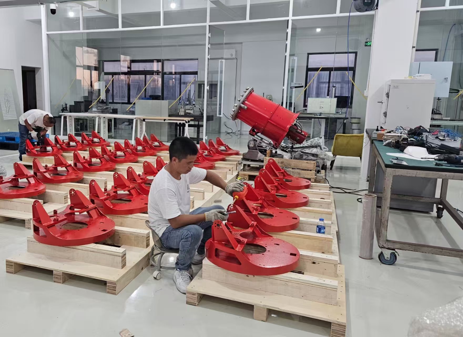
Rohre supplies turbine equipment for integration into your fire protection system. Agree the technical and documentation requirements before the configuration is released.
Share the project brief
Provide the application, layout, water supply, electrical conditions, controls and required approvals.
Agree the equipment
Confirm model, options, interfaces, drawings, testing scope, branding requirements and supply boundaries.
Define the handover
Agree packing, shipment documentation, installation information, spares and any requested commissioning support.
System design, site installation, fire detection logic and project approvals must be assigned explicitly in the project scope. Equipment supply does not automatically extend an existing system certification.
Specify what you want verified before shipment.
Include the required inspection and test items in the purchase specification. The agreed inspection plan defines the test method, acceptance criteria and records.
- Water duty: measured flow and inlet pressure, with nozzle configuration and test conditions recorded.
- Movement: rotation and tilt travel, limit functions, and position feedback where supplied.
- Controls: agreed commands, interlocks, alarms and loss-of-communication behavior for the selected package.
- Mechanical fit: mounting dimensions, connection details, equipment mass and configuration identity.
- Documentation: model-specific drawings, wiring information, inspection records and agreed service documents.
- Maintenance planning: access to nozzles, water strainers, drives and electrical equipment, plus spare-parts identification.
Equipment functional testing and application fire-performance testing answer different questions. Define both evidence requirements where relevant; a functional test does not establish extinguishing performance for the intended hazard.
Technical resources
Download the brochure. Review the technical data.
Start with the technology overview, compare the models, then request the drawings and supporting documents for your project.
Model technical data
Water duty, connection sizes, movement limits, utilities and dimensions.
General arrangement & mounting data
Installation envelope, base interface, operating weight and loads.
Controls & electrical information
Load schedule, wiring requirements, commands, feedback and signal list.
Performance evidence
Watch the outdoor spray demonstrations and request model-specific test data and conditions.
Installation, operation & maintenance
Installation requirements, inspections, maintenance and recommended spare parts.
Certification & project documentation
Identify the required documents and verify their applicability to the supplied equipment.
Frequently asked questions
Practical answers for your engineering team.
How do TT-200, TT-694 and TT-694S differ?
TT-200 is a freshwater configuration rated at 200 L/min with a DN50 inlet. TT-694 is a freshwater configuration rated at 694 L/min with a DN100 inlet. TT-694S has the same listed operating parameters as TT-694 and is suitable for seawater service on offshore platforms. All three have a rated operating pressure of 12 bar.
Does this equipment require a high-pressure water mist pump?
Use the turbine inlet duty to select the water supply. All three configurations have a rated pressure of 12 bar. Account for pipe losses, elevation and simultaneous flow demand when defining the upstream pump duty.
Can the turbine be mounted above the protected area?
An elevated fixed installation can be reviewed using the model’s aiming envelope, support loads and site layout. Confirm that the spray can reach the required area without obstructions and that inspection and maintenance remain accessible.
Does the reference spray distance define the protected area?
No. Spray distance is not a fire-protection coverage radius. Application performance depends on the hazard, nozzle configuration, pressure, aiming angle, wind and installation geometry. Request the relevant test conditions and evidence for your design.
Which model can use seawater, and is foam supported?
TT-694S is suitable for seawater service on offshore platforms. All seawater-wetted parts on TT-694S are made of SAF 2507 super-duplex stainless steel. TT-200 and TT-694 are the freshwater configurations. Specify the seawater conditions and offshore installation requirements with your enquiry. Foam compatibility and foam-related performance require separate technical confirmation.
Can the controls connect to our PLC or fire detection system?
Send your required commands, feedback signals, interlocks, fault handling and communication protocol. Compatibility is established by an interface review for the selected model and control package.
Can the equipment operate below 4°C?
The standard ambient range is 4 to 50°C. An optional heating concept for −40°C outdoor conditions uses dry pipework and 10 mm insulation. The supplied comparison lists on-demand preheating and continuous heating; rapid activation with continuous heating depends on normal power and heat-tracing operation. Confirm the complete assembly’s operating limits and cold-start performance for the project.
What is included in the supply?
The agreed equipment schedule defines the turbine, control panel, remote control, feedback, heating and documentation. Site installation, supporting structures, external piping, power distribution and commissioning services must be defined separately.
What should we send for a technical proposal?
Provide the project country, hazard and protection objective, site plan and elevation, mounting location, available water pressure and flow, electrical supply, ambient conditions, controls, quantity and required documentation.
How are lead time, testing and spare parts confirmed?
They are agreed against the final configuration and project requirements. Include your target delivery date, inspection points, documentation needs and spare-parts expectations in the enquiry.
Discuss your project
Tell us what your project needs.
Send your project details directly to our team. Include a drawing or specification if available, and we will review the model, installation and control requirements with you.
Attach a PDF, Word, Excel, JPG or PNG file up to 10 MB. Please review our Privacy Policy before sending personal information.