In some seawater RO systems, the available feed pressure fluctuates or is too low to supply the high-pressure pump reliably. When this happens, we add a seawater multistage centrifugal booster pump upstream to provide a steady inlet pressure of 2–5 barg for the axial piston high-pressure pump.
The booster supplies the inlet pressure, while the RO high-pressure pump builds the pressure needed for reverse osmosis. For this arrangement, we recommend placing the final cartridge filter after the centrifugal booster and before the RO high-pressure pump. The booster head then needs to cover the losses through the filter and connecting pipework, with enough pressure remaining at the high-pressure pump inlet.
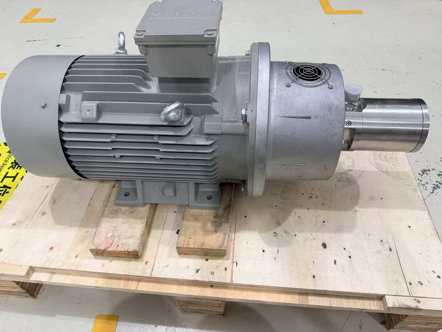
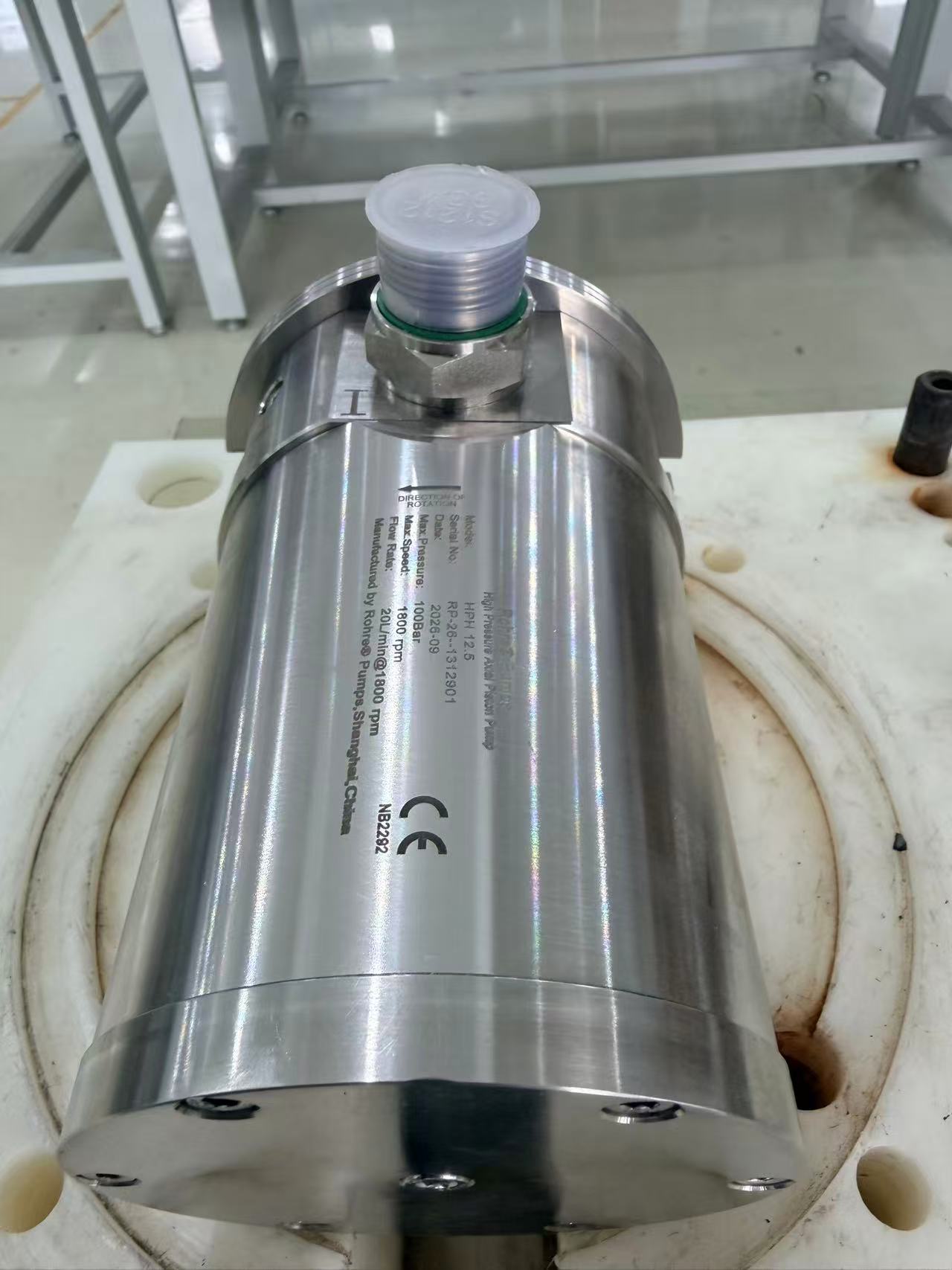
HPS39 package example: 31.45 m³/h at 80 bar
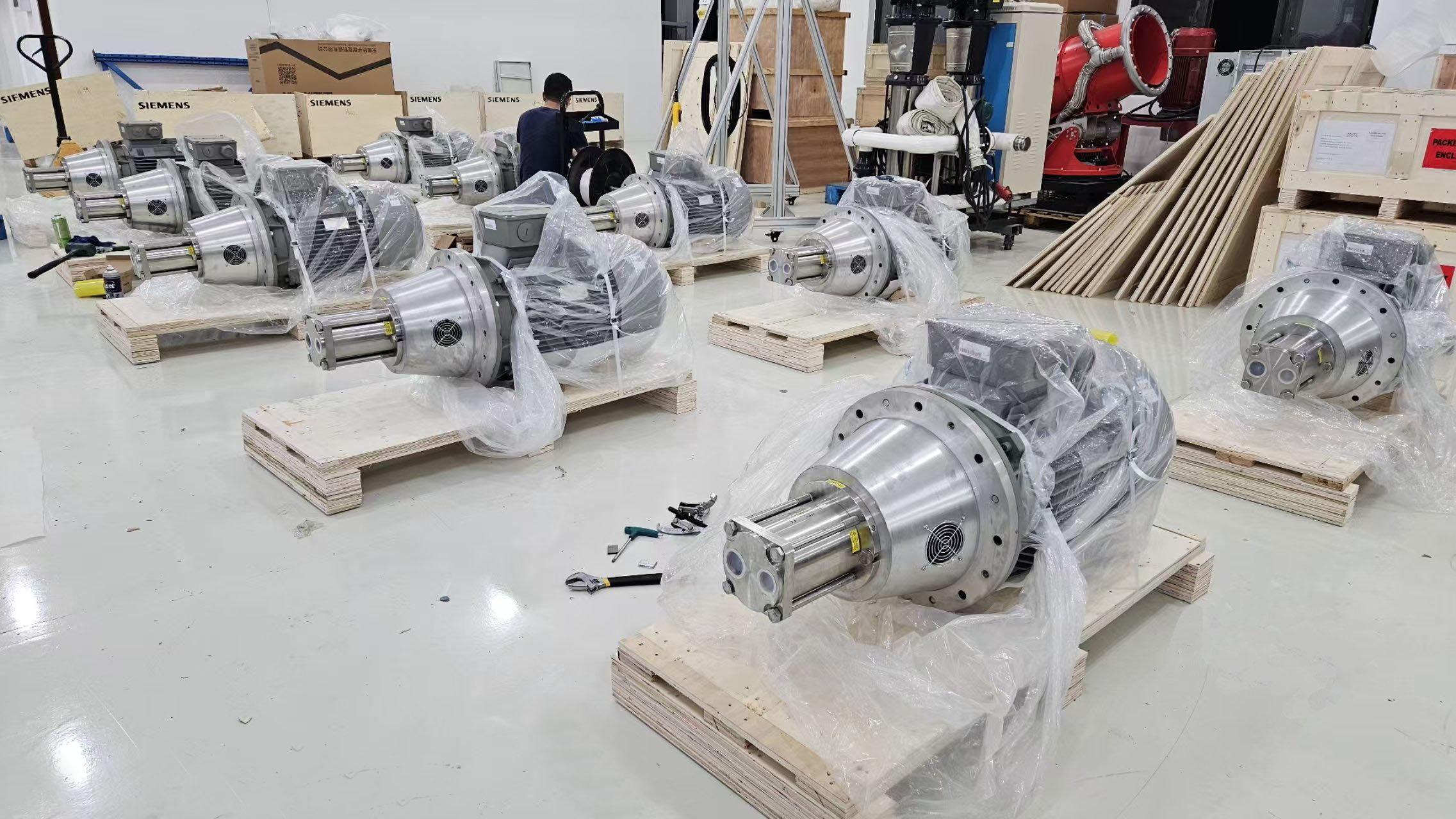
One example of this arrangement is an HPS39 seawater RO pump package configured for seawater with a salinity of 45,000 ppm. It combines the high-pressure pump with a 125 HP motor and soft starter, a multistage centrifugal feed booster and a 5 µm cartridge filter.
| Item | Project configuration |
|---|---|
| High-pressure pump | Rohre HPS39 axial piston seawater RO pump |
| Flow | 31.45 m³/h |
| Working pressure | 80 bar |
| Target pump shaft speed | 1,200 rpm |
| Medium | Seawater, salinity 45,000 ppm |
| High-pressure pump inlet pressure | 2–5 barg during operation |
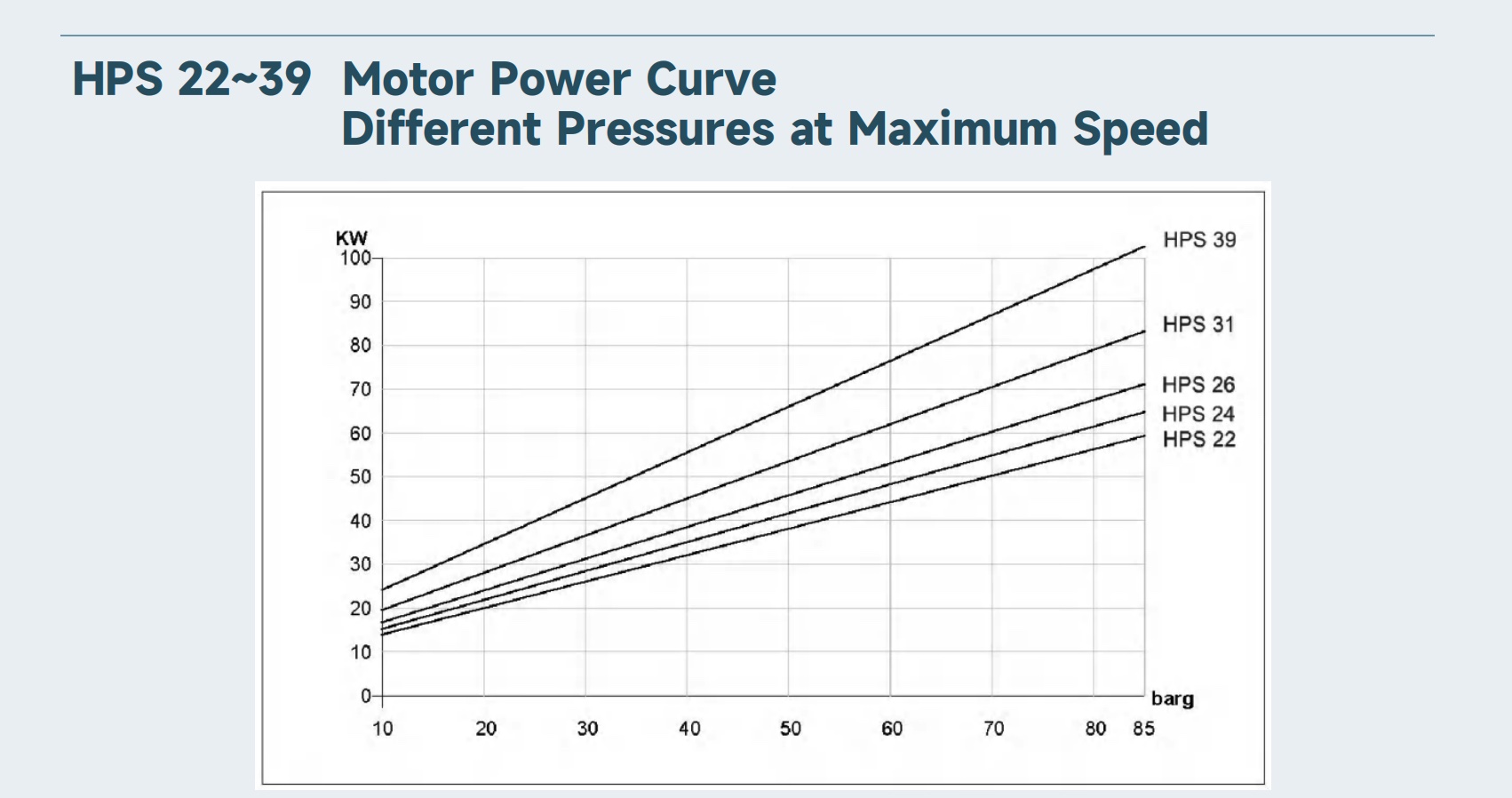
| Motor | 125 HP, approximately 93.2 kW; 460 V, 60 Hz, three-phase |
| Starting method | Soft starter; no VFD for the high-pressure pump motor |
| Feed booster | Multistage centrifugal pump; preliminary selection at 31.45 m³/h, with head determined by the available feed pressure and system losses |
| Cartridge filter | 5 µm; 18 × 40-inch cartridges; seawater duty at 31.45 m³/h |
How we select the feed booster
The booster has to supply the full 31.45 m³/h required by the HPS39. We then select its head from the available feed pressure, the pressure lost through the filter and piping, and the pressure needed at the high-pressure pump inlet.
As the cartridges collect solids, the pressure drop across the filter increases. We calculate the clean-filter loss at 31.45 m³/h and the higher loss allowed before cartridge replacement, using the data for the selected cartridges and housing. The booster needs enough head to maintain the HPS39 inlet pressure at that higher loss. Otherwise, a selection that works with new cartridges can leave too little pressure at the high-pressure pump as the filter loads up.
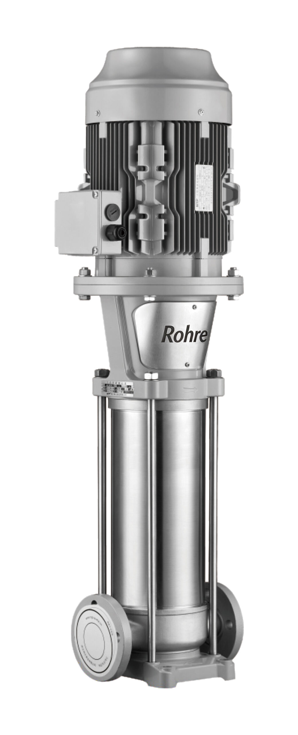
The booster adds pressure to the incoming supply, so a rise or fall in feed pressure can also affect its outlet pressure. We therefore look at two conditions: the lowest feed pressure with a loaded filter, and the highest feed pressure with a clean filter. The pump head and pressure-control arrangement need to keep the HPS39 inlet within 2–5 barg in both conditions.
We take the inlet-pressure reading close to the HPS39, after the final filter and with water flowing. A gauge upstream of the filter cannot show how much pressure is lost across it. For the starting sequence, we recommend bringing the feed supply up to pressure before starting the HPS39 and using a low-inlet-pressure interlock at the pump inlet.
The cartridge filter and its installation
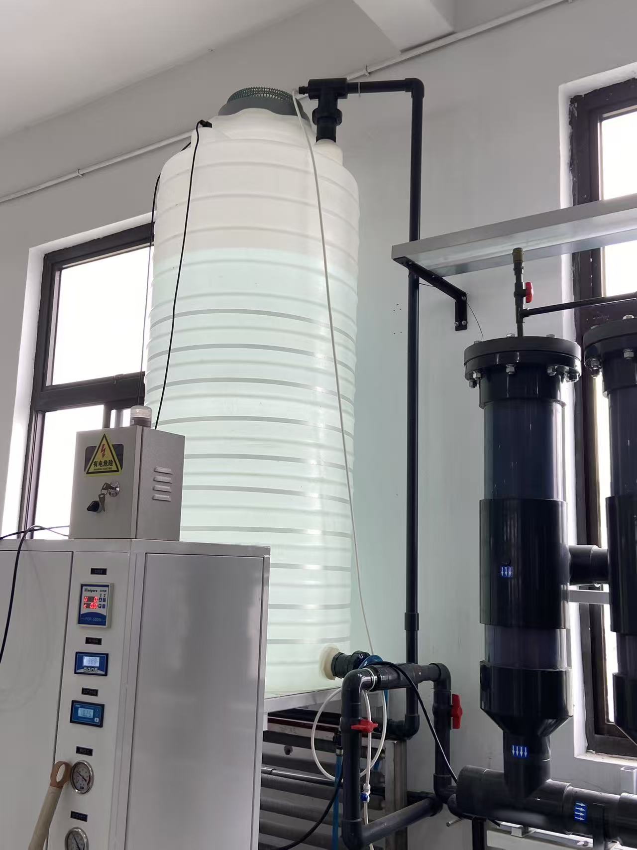
This configuration uses a 5 µm cartridge filter with eighteen 40-inch elements, sized for 31.45 m³/h of seawater. The housing, seals and other wetted components need to suit the seawater. Filter differential pressure should be monitored alongside the HPS39 inlet pressure, so the cartridge replacement limit leaves enough pressure for the high-pressure pump.
Putting the fine filter on the booster discharge side keeps its pressure loss out of the centrifugal pump’s suction line. If a coarse strainer is fitted upstream to protect the booster, its loss still belongs in the suction-pressure calculation. The booster needs enough suction pressure to avoid cavitation, even as that strainer collects debris.
The layout also needs room to open the housing and withdraw the cartridges, with the motor and connecting pipework clear of that access. For a containerized SWRO installation, this service space has to fit inside the container along with the pump and its connections.
Starting the 125 HP motor
The high-pressure pump motor is rated at 125 HP, approximately 93.2 kW, for a 460 V, 60 Hz, three-phase supply. We use a soft starter to reduce the starting current by ramping up the motor voltage during run-up. This package does not require a VFD for the high-pressure pump motor.
The 1,200 rpm figure is the target pump speed. We match the motor’s actual full-load speed and the drive arrangement to that target; the soft starter handles starting rather than continuous speed control.
Send us your required flow, RO working pressure and available feed-pressure range. We can work out the high-pressure pump, booster and filter configuration together.