Two water-mist installations can require the same maximum pressure and still need different pump packages. The difference may be the water flow, the sections that operate together, the inlet supply or the way the system starts. Those conditions determine the pump size and the equipment around it.
At Rohre, we work from your system’s hydraulic demand to select the high-pressure pump and discuss the motor, connections and pump-side accessories included in the assembly. The aim is a package that fits your layout and operating requirements, with a clear handover to the system controls. Our high-pressure water-mist pumps (HPH Series) provide the starting point for that selection.
Table of Contents
ToggleCompare the flow at the pressure and speed you will use
A maximum-pressure rating describes an operating limit. It does not tell you how much water the pump delivers at the speed available from your drive. For an axial piston pump, displacement and shaft speed establish the theoretical output; internal leakage also affects the delivered flow. That is why the catalogue flow, its pressure and its speed belong together.
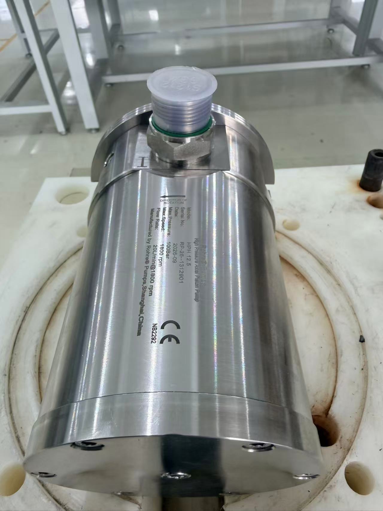
The following HPH values are all listed at 16 MPa (160 bar) and 1,500 rpm. The final column is the model’s maximum speed, not the speed used for the flow figures.
| HPH model | Catalogue flow at 160 bar and 1,500 rpm, L/min | Maximum shaft speed, rpm |
|---|---|---|
| HPH 8 | 11.0 | 3,000 |
| HPH 10 | 13.8 | 3,000 |
| HPH 11.5 | 15.8 | 3,000 |
| HPH 12.5 | 17.3 | 3,000 |
| HPH 20 | 27.6 | 3,600 |
| HPH 25 | 34.5 | 3,600 |
| HPH 32 | 44.2 | 3,600 |
| HPH 40 | 55.2 | 3,000 |
These model groups have a listed outlet-pressure range of 30–160 barg. The HPH catalogue contains the model tables and curves. We use the data for your required duty and drive speed when developing the selection, rather than treating the maximum speed as the normal operating point.
The pressure also needs a defined location. If your hydraulic calculation gives the pressure required at the nozzles, the pump-outlet requirement includes the distribution losses and elevation effects identified by your system designer. Starting from that pump-outlet duty keeps the pump selection aligned with the system calculation.
The smaller demand matters as well as the largest
An axial piston pump continues to displace water while its shaft turns. If downstream demand falls while pump output remains unchanged, the surplus flow needs a designed route. Simply restricting or closing the discharge does not make a positive-displacement pump behave like a centrifugal pump; it can drive the pressure up.
This makes the operating sequence important to the pump package. A steady demand and a system with several permitted demand combinations may need different pressure-control or unloading arrangements. We can work through the pump-side response with your system designer, including the discharge protection and return path. The chosen arrangement must fit the project’s fire-system design and approval requirements.
| Your system’s operating condition | What changes in the pump-package discussion |
|---|---|
| A defined, steady discharge duty | Pump output and motor loading can be evaluated around that duty. |
| Several required demand combinations | Each combination affects the required output, pressure regulation and any surplus-flow path. |
| More than one pump running | The inlet supply and electrical supply need to support the specified combination, not just an individual pump. |
| A duty/standby arrangement | The start commands, status signals and changeover responsibility need to match the system controller. |
Where variable speed is permitted by the system design, the usable speed range still has to suit the pump and motor. Speed control and overpressure protection perform different jobs. The package needs the appropriate protection even when a drive adjusts the normal output.
Worked configuration example: two demand levels on one package
This is an illustrative selection exercise, not a delivered-project specification. Assume a system designer has established two pump-outlet duties: 30 L/min and 15 L/min, both at 140 barg after allowing for distribution losses. The available drive speed is initially 1,500 rpm. These are specified operating cases; the pump selection does not determine which fire zones may operate together.
Start with the catalogue table above. At its 160 bar reference condition, HPH 20 delivers 27.6 L/min and HPH 25 delivers 34.5 L/min at 1,500 rpm. Those figures make HPH 25 the more promising starting point for the larger duty. Because this example operates at 140 bar, we would use the corresponding curves or test data to establish the actual output and shaft power before finalizing the selection. The 160 bar values are a screening reference, not claimed 140 bar test results.
| Configuration route | What it means for this example | Decision it resolves |
|---|---|---|
| HPH 20 with the existing fixed-speed drive | The published 160 bar reference flow is below 30 L/min. The 140 bar curve is needed to establish whether the actual duty can be met. | A pressure rating alone is insufficient to accept this pump at the available speed. |
| HPH 25 with fixed speed and designed flow regulation | Use its output at 140 bar to size the surplus-flow path for both the 30 and 15 L/min cases. | Retaining fixed speed shifts more of the configuration work to regulation, return piping and heat management. |
| A variable-speed arrangement, where permitted | Check the pump and motor operating limits at both duties, then evaluate the transition between them. | Changing speed may reduce surplus flow, but the required low-flow point must remain inside the usable speed range. |
To see why the smaller duty matters, suppose a fixed-speed arrangement delivers 34 L/min at 140 bar. Supplying a 15 L/min demand leaves 19 L/min to be diverted. Reducing that surplus from 140 barg to a near-atmospheric tank dissipates approximately 140 × 19 ÷ 600 = 4.4 kW of hydraulic power as heat. The assumed 34 L/min is for this calculation only. Return duration, tank volume and heat removal therefore affect whether that arrangement is suitable.
A short return loop directly to the inlet can accumulate heat, so the return destination belongs in the package layout. Normal flow regulation and emergency overpressure protection also have separate functions; the normal control method must not depend on routinely using a safety-only relief device.
For this example, the useful proposal would identify the selected pump, output at both duties, drive arrangement, normal regulation method and return destination. The fire-system designer determines the permitted control sequence, including start, stop and standby changeover. Pump-side speed response and status signals are then matched to that sequence. Operating tolerance and transient pressure must remain within the ratings of the pump and every supplied component.
Give the pump a dependable water supply
HPH pumps use water for lubrication and are not self-priming. A tank that is full at rest does not, by itself, establish the inlet condition during operation. Tank level, pipe length, fittings and filtration all affect the pressure available at the running pump. A shared supply can change that condition again when another pump starts.
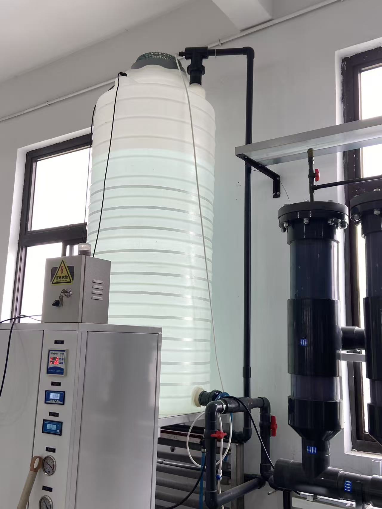
We consider those inlet conditions alongside the chosen model. A compact skid still needs adequate inlet pipework and a practical way to fill and vent the circuit. Water quality and filtration are part of protecting the internal running surfaces; the arrangement has to protect the pump without starving its inlet.
The installation and operating information explains the general filling and handling principles. The instructions applicable to the selected model and assembly establish its operating limits. This work belongs in the layout discussion, while the inlet route and connection positions can still be adjusted.
Make the assembly fit the equipment around it
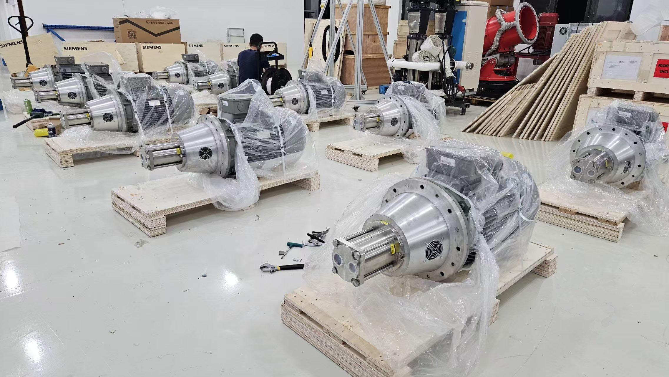
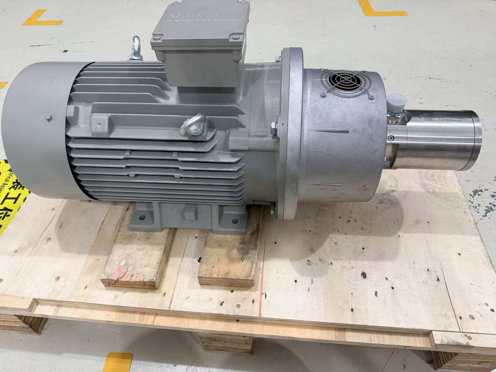
We can supply the pump or discuss an assembly with the motor, coupling, bell housing, guarding, base and connections. If you use your own motor, we check the pump parameters and mechanical interface against its specifications and can supply the matching coupling and bell housing. The layout identifies the final water connections after any supplied adapters.
Service access deserves space too. A pump may fit inside the enclosure but still be difficult to remove if a pipe crosses the coupling or a filter blocks the access route. Reviewing those features before the frame is built gives your team a better basis for installation and later maintenance.
The signal interface identifies the start commands, running indications and fault signals exchanged with the system controller. Their functions and response follow the project’s approved fire-system control design.
Test the conditions the package is being supplied for
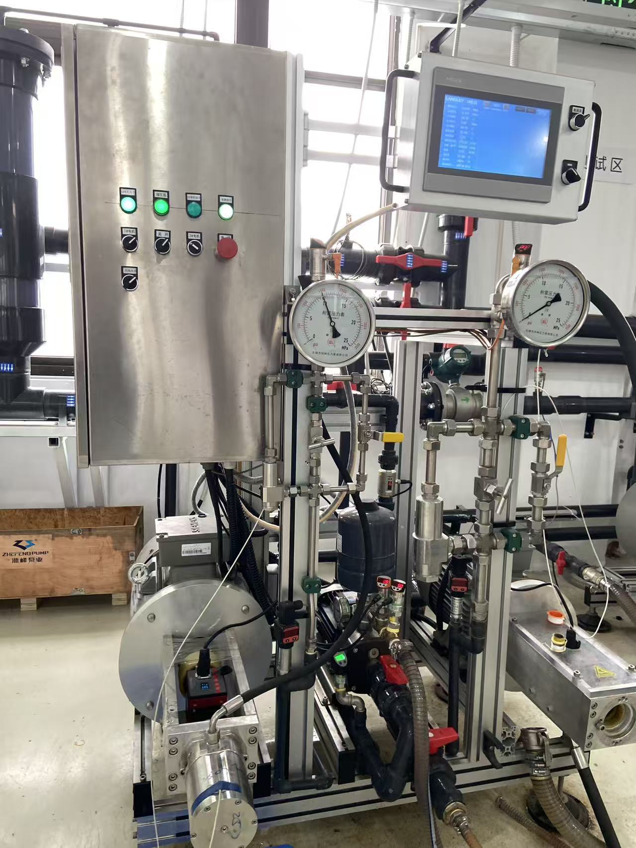
For acceptance, the agreed operating points should include flow, pressure, speed and inlet conditions together. If pump-side controls are supplied, their functions and test interface also belong in the test scope.
Factory testing covers the supplied pump or assembly. Integration and site testing then address the actual water supply, pipework, power and system controls. For a listed or approved fire-protection system, the proposed pump package also needs to fit the permitted system configuration. We can discuss the pump-side documents with your OEM team as part of the proposal.
Start with the duty and the layout you already have
Send us your pump-outlet flow and pressure requirements and the available layout. If several pump or demand combinations are required, include those operating cases. We can begin with the pump and drive selection, then work through the connections and the pump-side scope with you.
You can use our pump selection form or contact the Rohre team with your existing project documents.